I designed this from the ground up as a learning exercise as much as anything else. And, honestly just because it seemed like a fun project. I had no cable chain experience before making this so I am not sure exactly how the chain is supposed to behave but I think this one works pretty well.
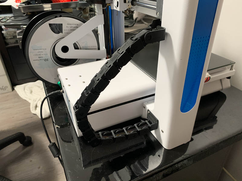
This cable chain is really not needed but I didn’t like the way the x-axis motor wires rubbed up against the hotbed and sometimes the hotbed connector. The cable chain positions the wires away from the hotbed and controls its position at all times to avoid any conflict with the bed, bed connector or printed parts.
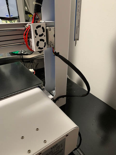
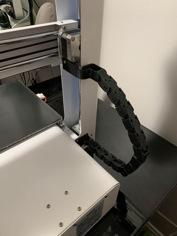
The assembly uses existing screws on the printer to hold everything in place. So no new hardware is needed.
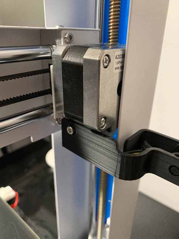
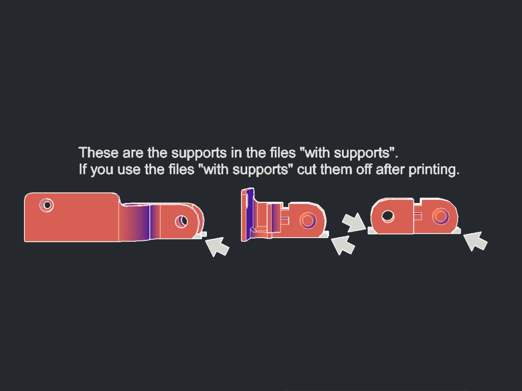
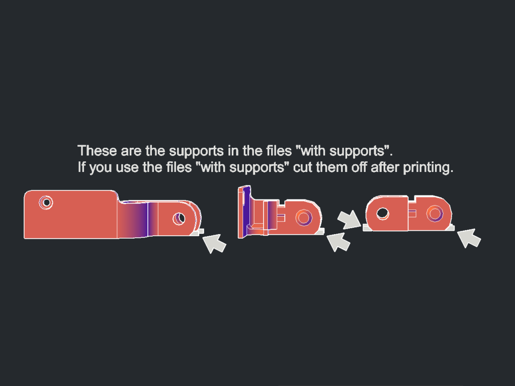
I was having a lot of difficulty printing the very small overhangs used on the rounded edges of the parts. So I added a small wedge to serve as support which worked well but has to be clipped off with side cutters after printing. So I am including two sets of everything. One set has the support wedges and one set does not (for those who can print overhangs well).
The cable retaining clip that snaps into place after the wire is laid into the chain is designed to be snapped in and out relatively easily but they are small so hopefully you never need to take them out. If you do need to take them out pry under them with a small screwdriver or similar and it will pop out.
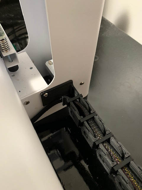
The JGAurora A3S uses 13 links plus the upper and lower attachments. I am pretty sure this will work on the A5 as well but will require more links (17 or 18 links).
Post-Printing
1. Remove the supports (if you printed the version that has supports)
Use your diagonal cutters (if you don’t have any get some, best $10 you will ever spend) to clip off the small support I placed under the front and back edges. See photo…
2. Snap together
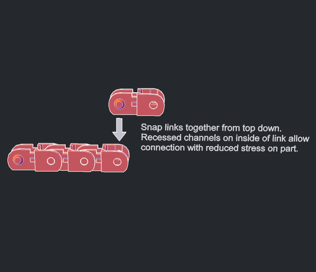
The links are designed to snap together with the inner link sliding into the outer link from the top. There are recesses in the inner side of the outer link to allow them to snap together with less stress.
3. Install on the printer
Before you start move the z-axis up to half height or higher. And, move the print head along the x-axis away from the x-axis stepper motor.
Remove the screw under the x-axis stepper motor and then re-install the screw through the top of the assembly as shown in the photo.
Remove the screw holding the x-axis wiring strain relief at the bottom (see photo) and re-install the screw (without the washer or strain relief) through the lower part of the assembly under it.
4. Load the cable and snap in the retainers
Position the x-axis cable into the cable chain trays and then place a clip onto each of the links.
Go print!

Leave a Reply